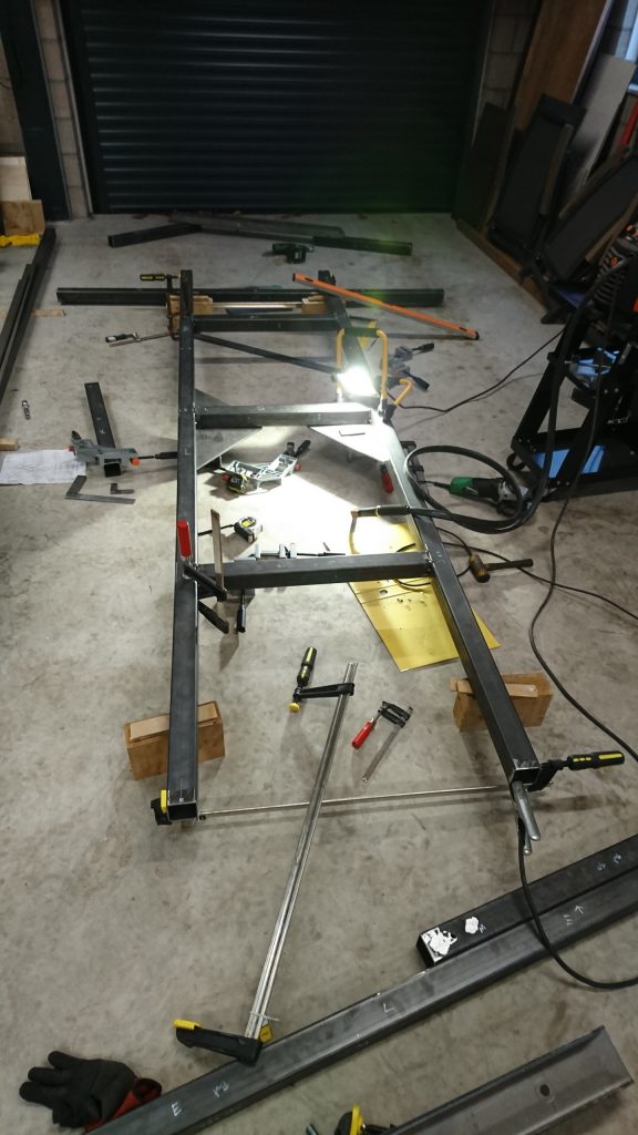
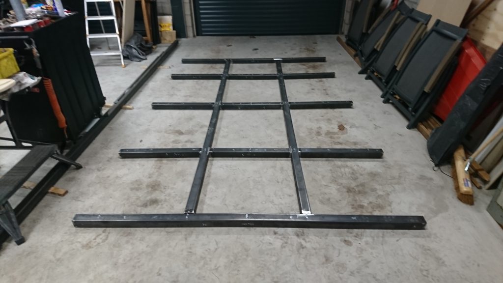
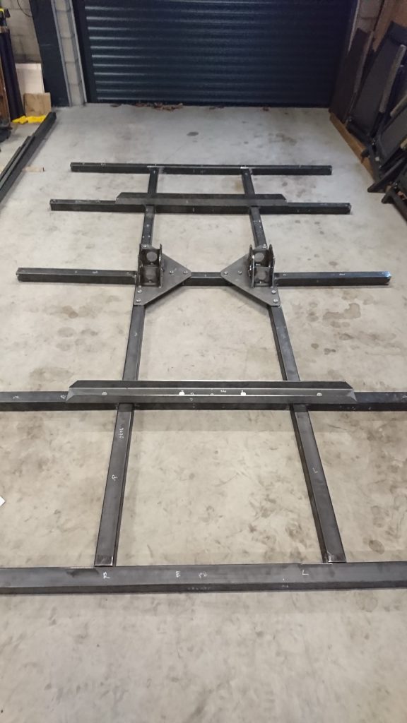
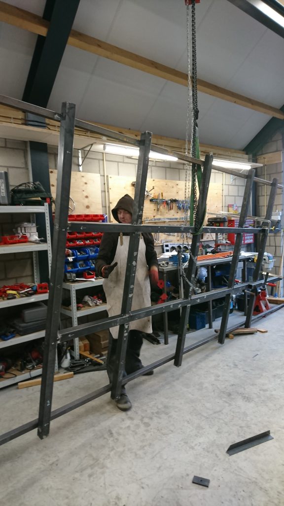
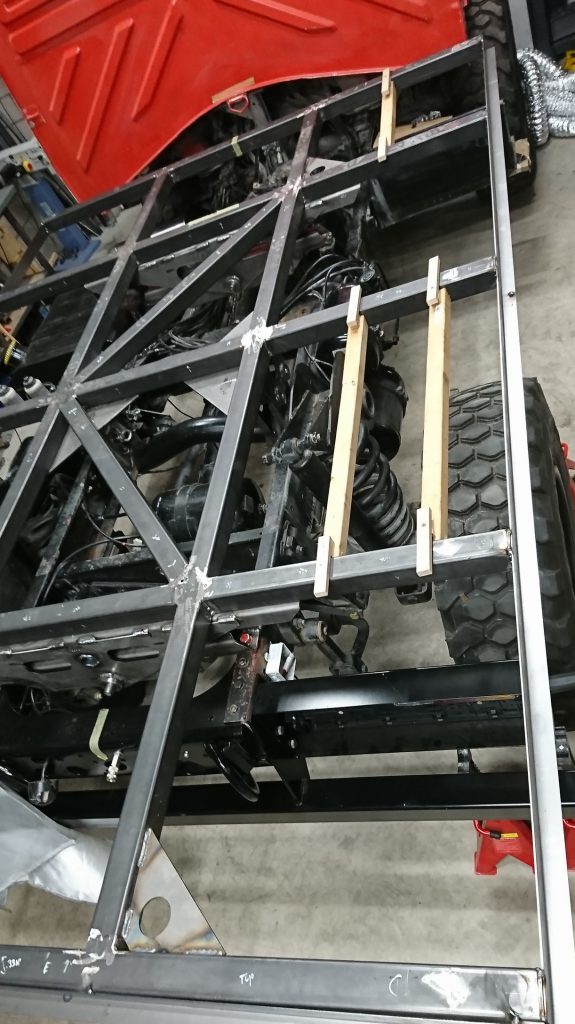
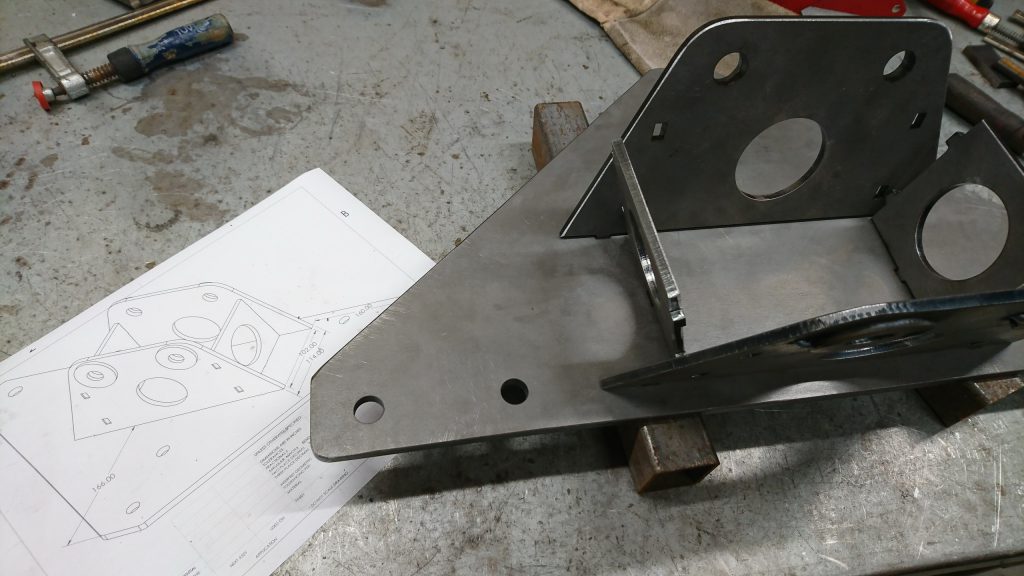
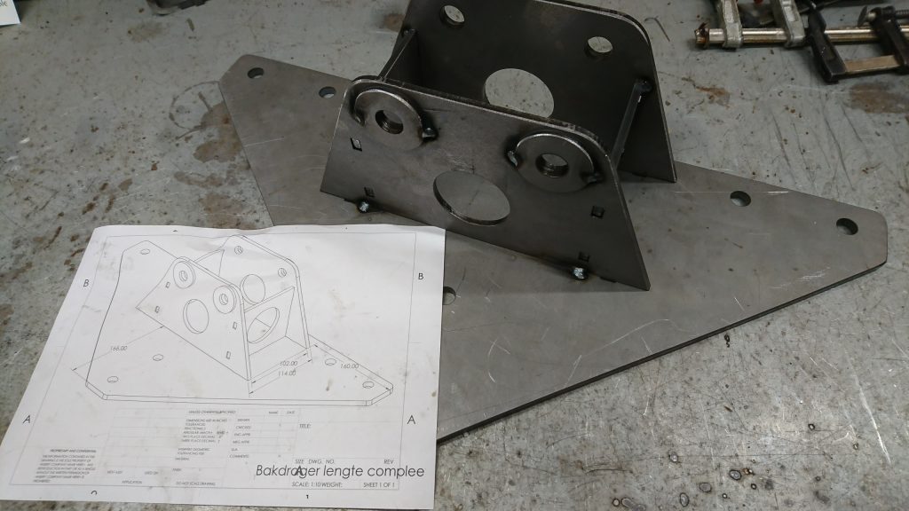
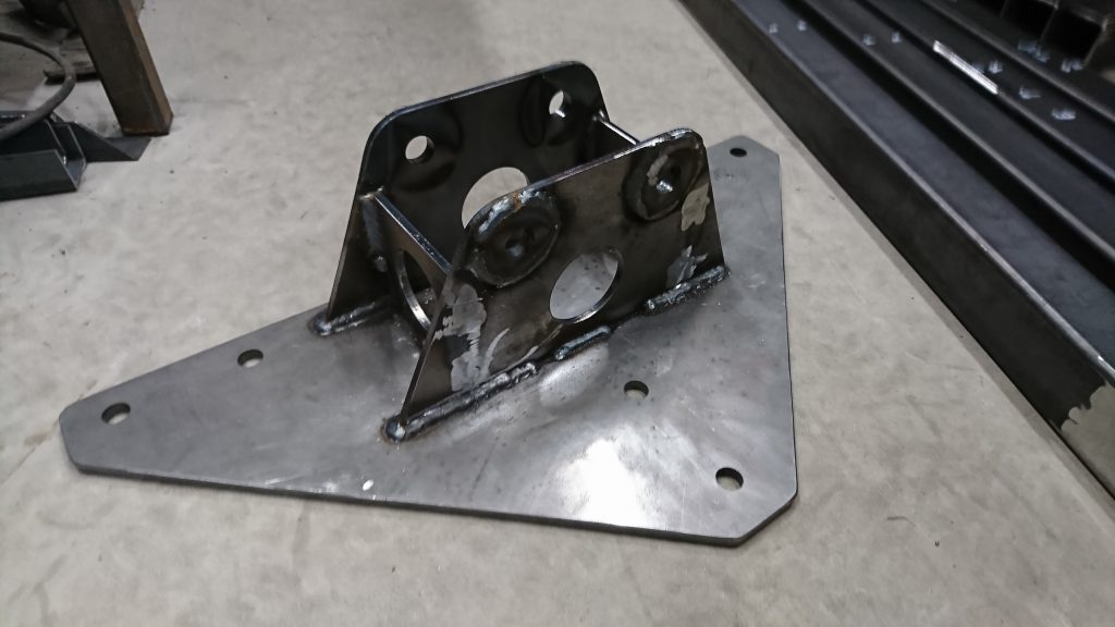
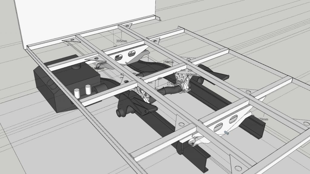
During the design phase, it was decided to integrate the subframe and the floor. The attachments in between are bolted into the chassis and the floor. It’s our job to make this possible.
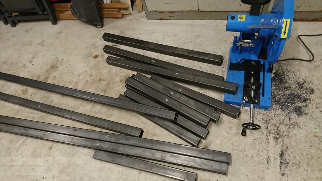
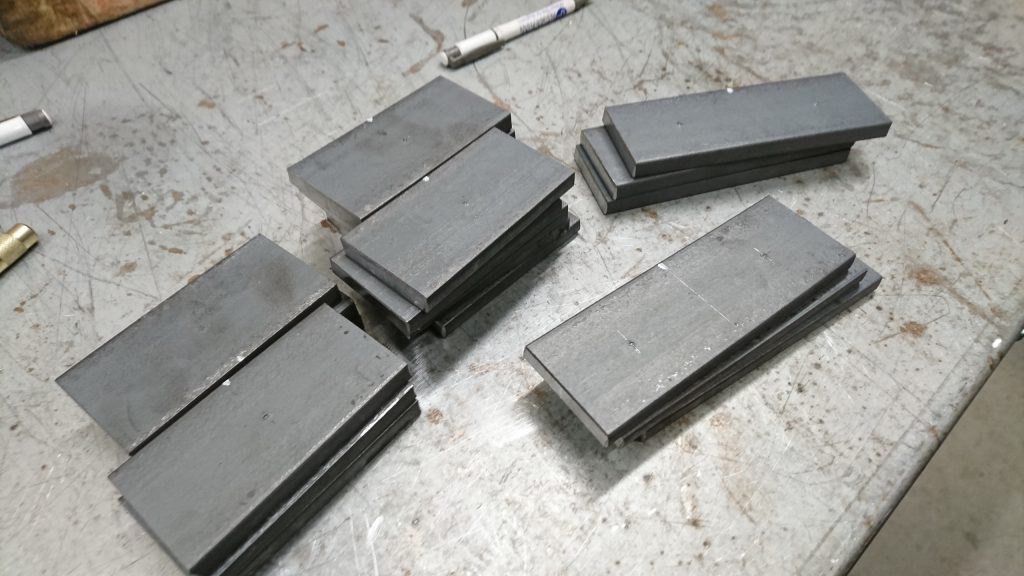
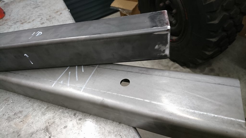
Step 1: lots of cutting of steel. Tubing for the frame, flat pieces for attaching it.
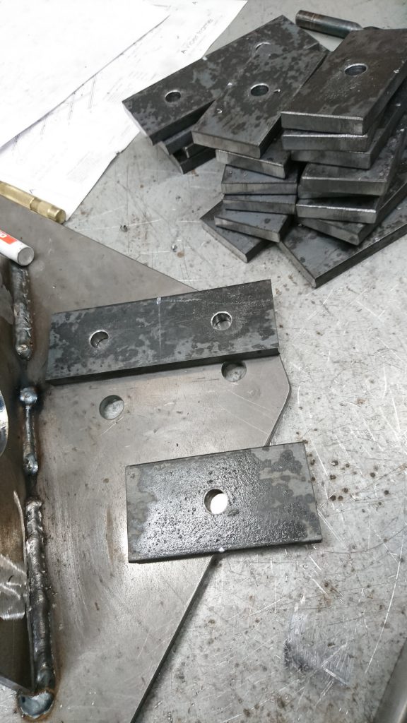
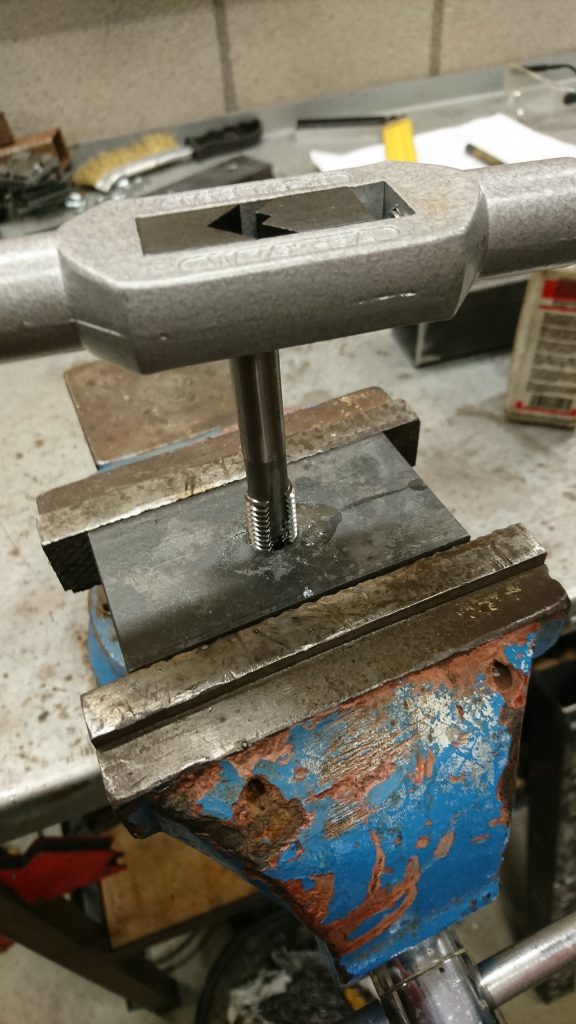
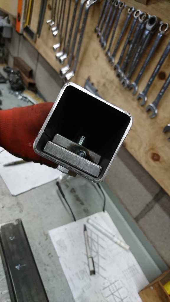
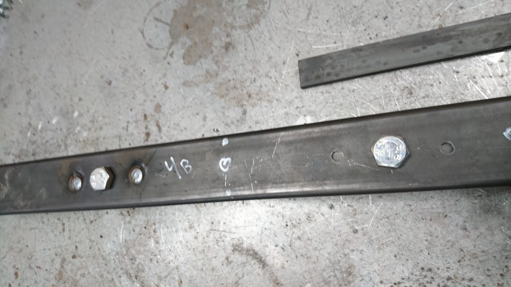
We’re drilling holes and tapping thread. The bolts will go through holes in the tubing into these pieces of flat steel with the thread.
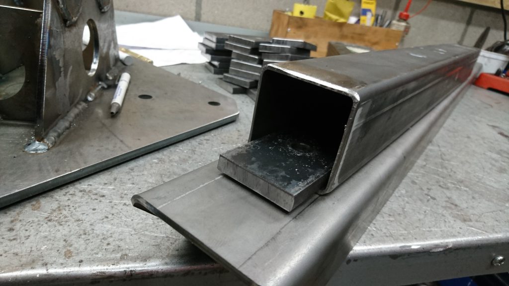
The flat pieces are shoved into the square tubing and fastened with bolts. The extra holes are used to weld the pieces of flat steel into the tubing. Later on, the bolt holes are be used to attach the floor to the chassis.
The pieces of square tubing are welded together and create the frame for the floor. A piece of angle iron is used for the sides, the camper body walls will rest on this.
And so we move forward in our project. 🙂

