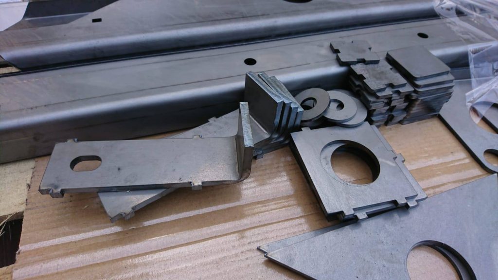
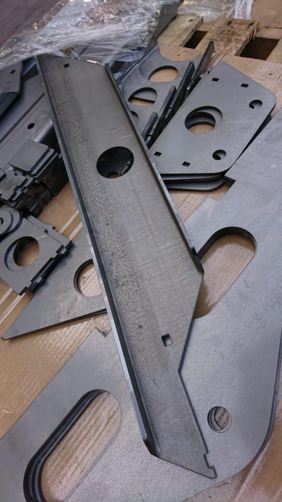
Cabine mount, part 1

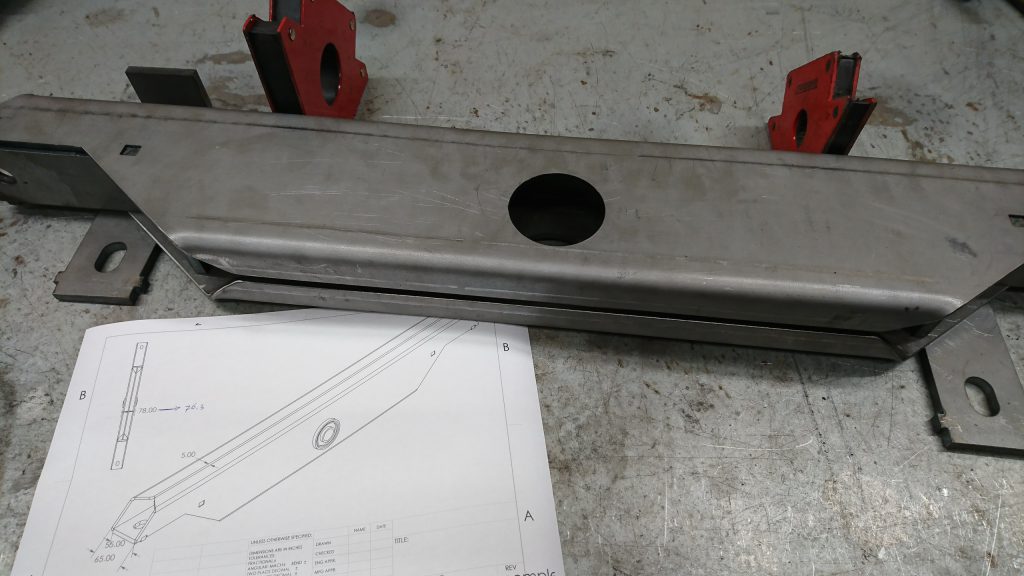
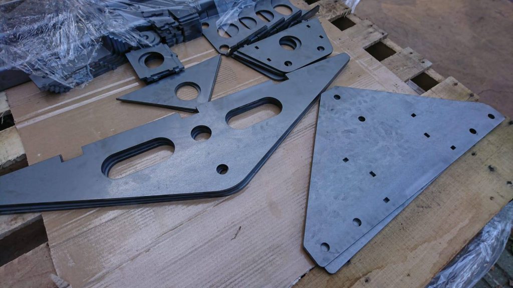
After designing and laser-cutting the parts, it’s time to put things together.

We’ll start with the crossbars on the chassis, one at the front and one at the rear. When putting the parts together, I notice that a mistake was made (by me): the front and rear mounting holes are distanced different and the size is different as well.
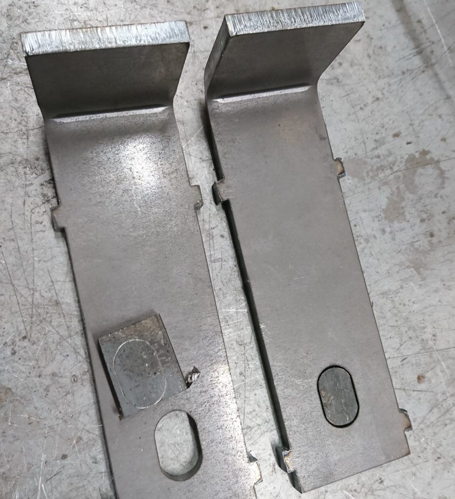
After welding the slots, new holes were drilled at the right location and the rear holes are enlarged.
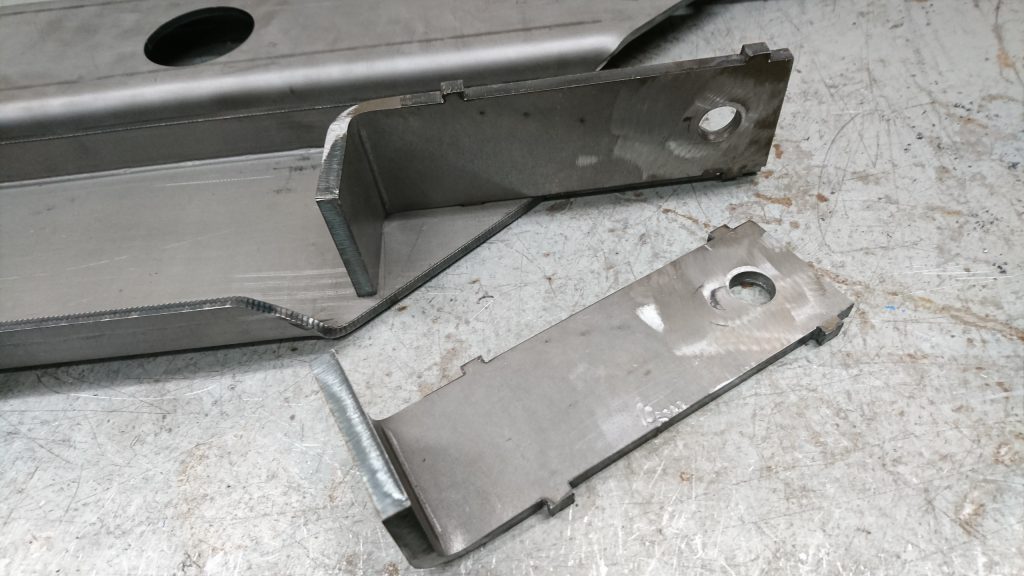
New holes!

Now everything can be put together!

Just like the design

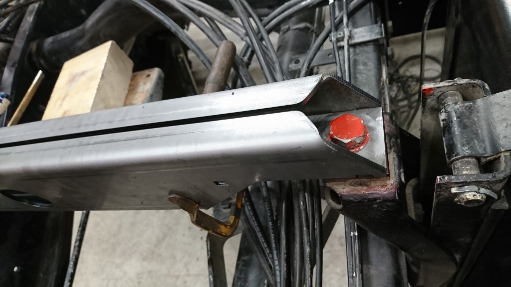
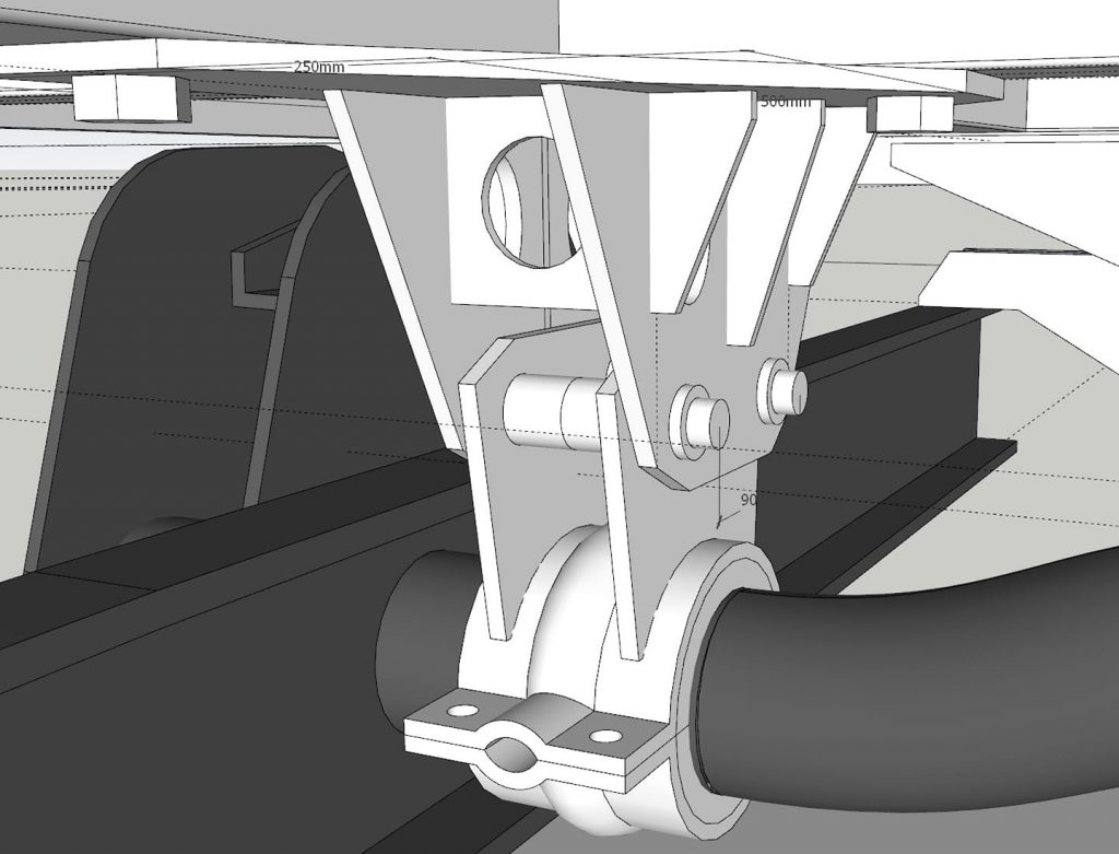
Welding, deburring and there, two finished crossbars. A vibration damper will be pushed into the hole and later on, a connecting rod will be used to keep the living area attached to the crossbar.
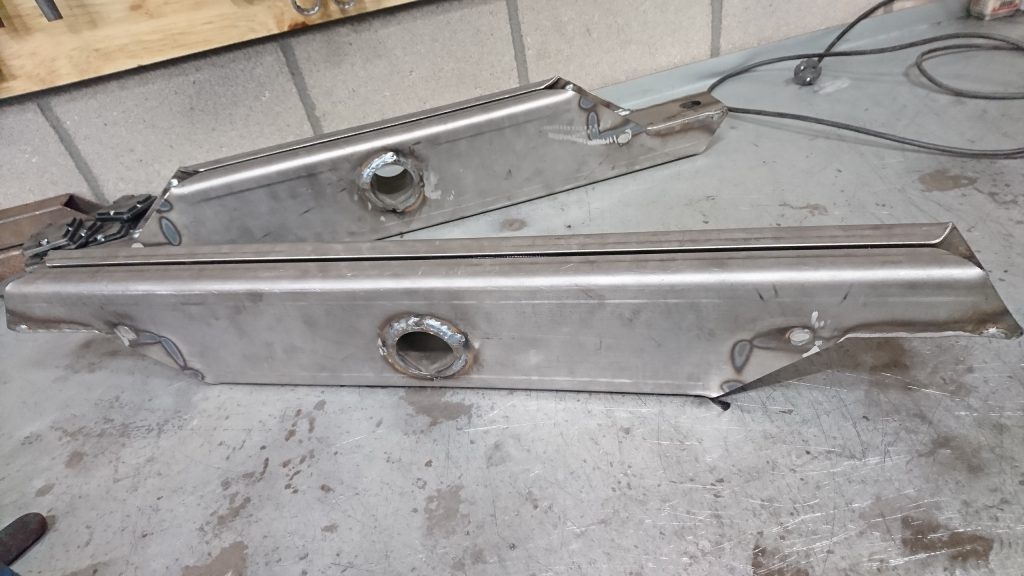
Two pieces finished!

Subframe design

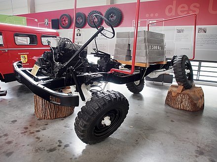
Unimogs have a very flexible chassis, excellent when driving in heavy terrain and it’s one of the reasons these vehicles are so good at it.

Flexible Unimog chassis

But of course, the living area, the cabin, shouldn’t twist as the chassis does, it will destroy the cabin. This requires a so-called ‘subframe’. The idea is that this will connect the cabin to the chassis without relaying the chassis movement to the cabin.

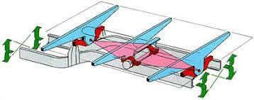
4-point attachment system

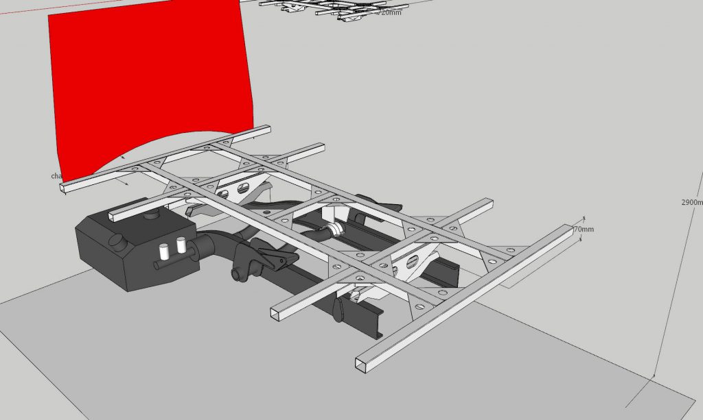
We’ll connect the subframe via a 4-point attachment system to the chassis, in a diamond shape. The front and rear connection are left/right flexible due to a pivot point, while the middle connections are forward flexible due to a rubber bushing.

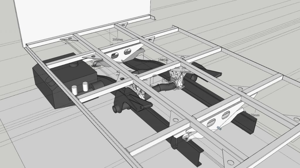
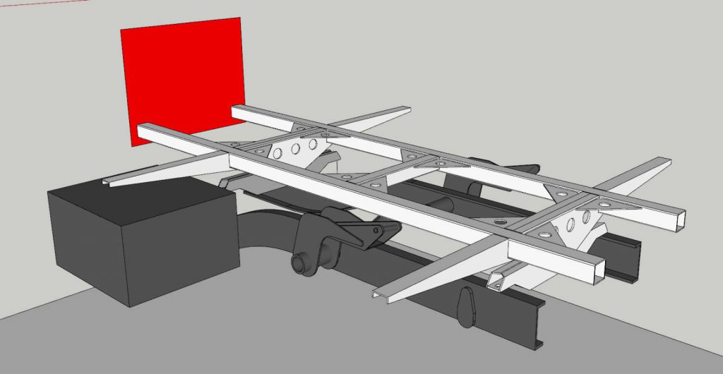
First subframe design, cabin should go on top of this

Martijn drew (part of) the Unimog chassis and designed a subframe. the idea was that the cabin would be mounted on top of this frame.

Later, we we heard the frame could be integrated in the floor, so the cabin would be slightly lower. And as it should be mounted as low as possible, we decided to do so.

After having all the parts laser-cut, it’s time to assemble!